


"Design a House with AutoCad Architecture 2021"
Published - Copyright© 2021 by Pantelis Skourtis
2.1.1- Create the Basement Outline
Open the drawing file you created in the earlier chapter 2.0.1 - Drawing Setup, under the name h21260_starting.dwg, and you have saved it in the path: C:/ACA/customDwg/house21-260_custom/h21260_starting.dwg.
On the website where you will be directed, on category Custom Drawings/ Basement locate the file h21260_starting.dwg, and click on the file name to download and open it.
Then save it under the name h21260_starting.
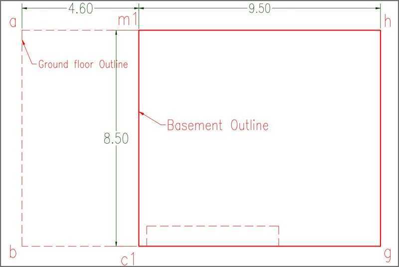
Now that the basic file is set up, you will start to design the layout of the basement floorplan for your project house21-260, as shown in Fig.2.1.1.1.
For the outline of the basement floor plan, you will draw a polyline in the shape and dimensions that are shown in Fig.2.1.1.1.
You could draw the outline (m1 c1 g h m1) line by line, but that is not very efficient. The best approach is to draw a polyline of given dimensions, as shown in Fig.2.1.1.1.
This polyline is the outline of the basement floor plan, that you design.
On the Application Status bar  , turn On the ORTHOMODE
  , turn Off display Drawing Grid
  (its color has to be grey), turn Off Snap mode
  (its color has to be grey), and turn On the Dynamic Input
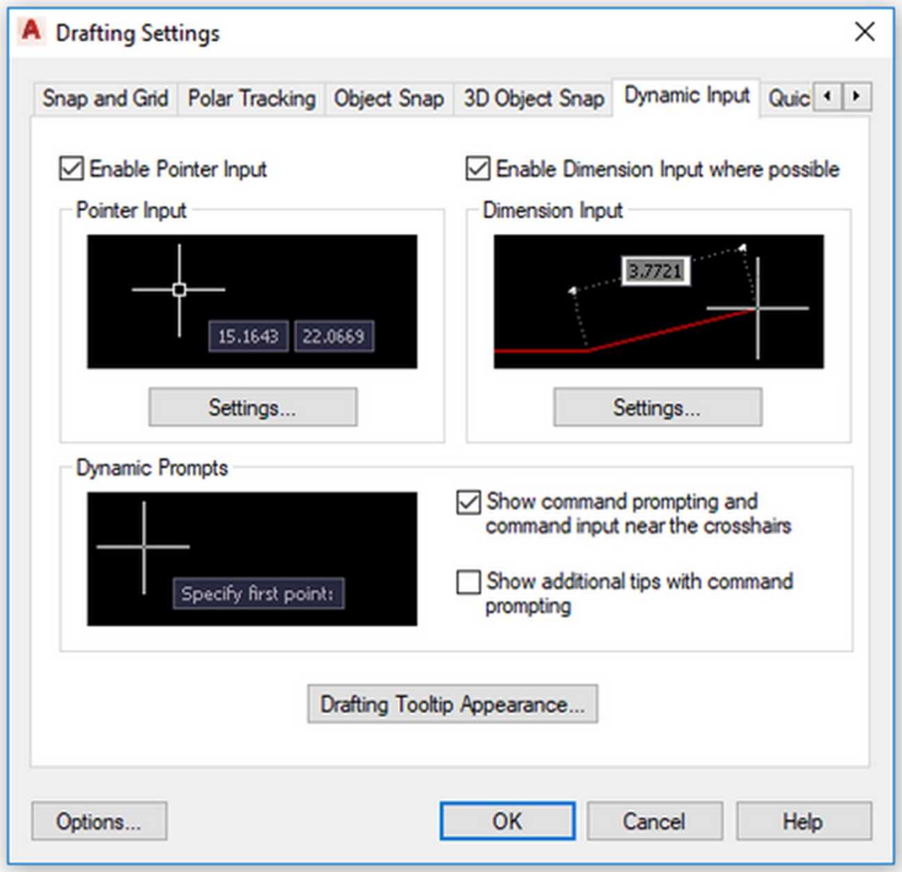
  , right-click on it and customize its settings as shown in Fig.2.1.1.2.
Create the layers
Now you have to create three new layers.
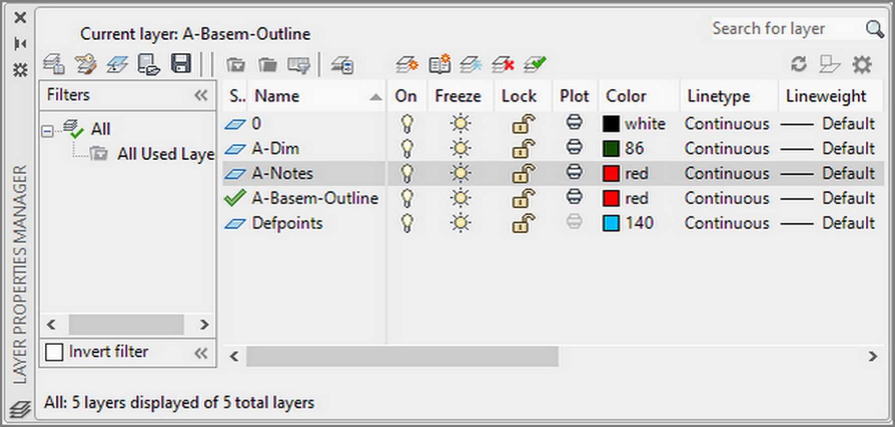
Create a new layer, with Name: A-Basement-Outline, Color: red, and make it current, a second layer with Name: A-Notes, Color: red, and another layer with Name: A-Dim, Color: 86.
To do this:
- Click Home tab ►Layers panel ► click Layer Properties icon

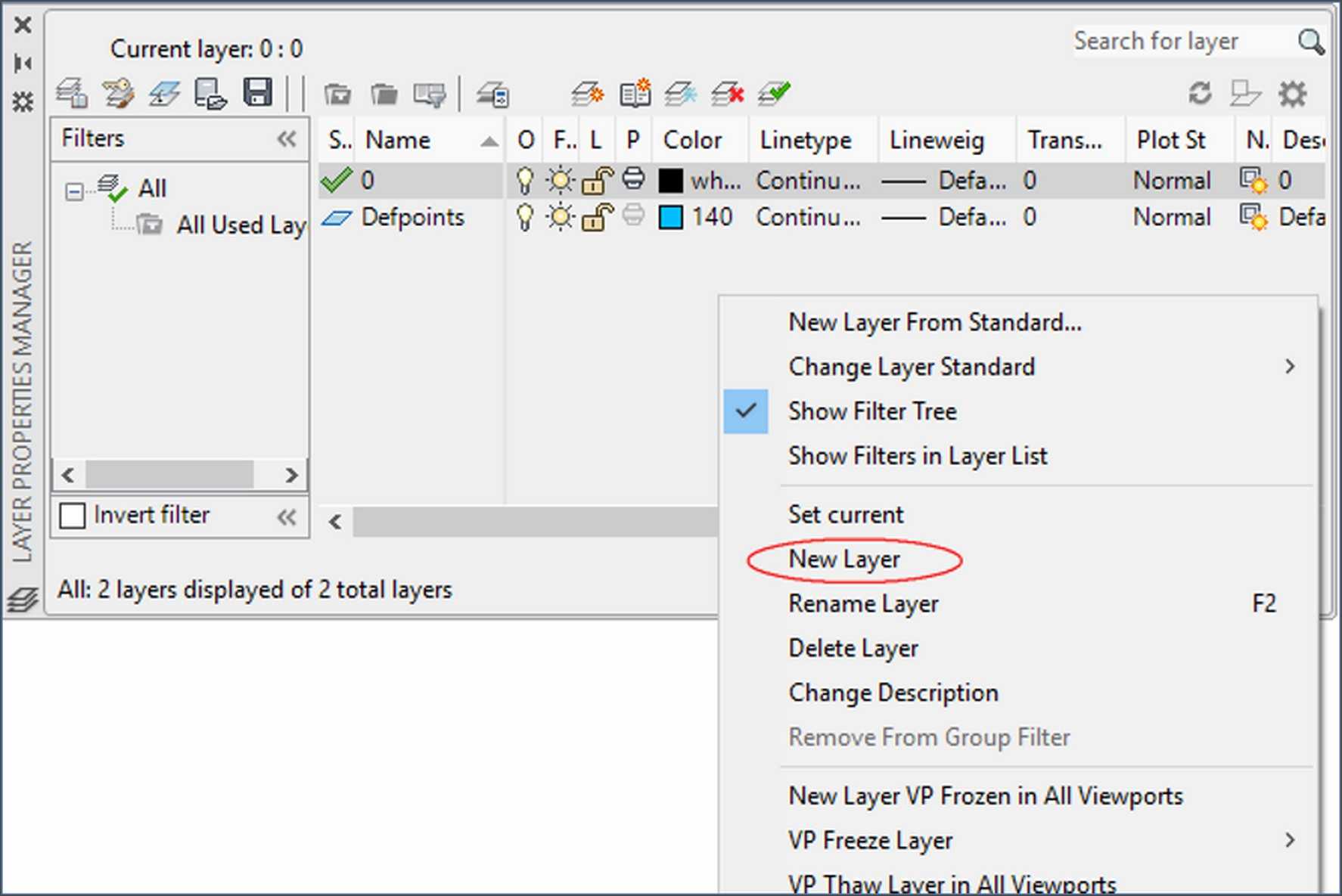
- Right-click on the 'Layer Properties Manager' window that will open ► and from the drop-down menu that will appear select New Layer (Fig.2.1.1.3) ► for the Name type A-Basem-Outline , for Color select red, and make it Current.
- Right-click on the 'Layer Properties Manager' ►select New Layer ► for the Name type A-Dim , for Color select 86.
- Right-click on the 'Layer Properties Manager' ►select New Layer ► for the Name type A-Notes , for Color select red, after that the Layer Properties Manager will be as shown in Fig.2.1.1.4.
- Close the Layer Properties Manager dialog box.
Draw the Polyline
To draw the polyline (m1 c1 g h m1), as shown in Fig. 2.1.1.1:
- Click Home tab > Draw panel > click Line (hover on)
 and from the drop-down menu select Polyline.
 - To Specify on the screen the Start point (m1) of the polyline type 24.60, 20.00, and press Enter (You will define a point (a) as a reference point for all your drawing.
From now on, keep in mind that you will use the same coordinates (20, 20) for the same point (a) in all drawings of this project.. - Move your cursor downward, type 8.50 (it is the length (m1 c1 to define a second point (c1), move your cursor right, type 9.50 (it is the length (c1 g)), and press Enter to define the third point (g), move the cursor upward and type 8.50 to define the fourth point (h), right-click and select, from the drop-down menu that will open, 'close' to close polyline (m1 c1 g h m1).
To display the maximum extents of all objects, as shown in Fig. 2.1.1.1: - On Ribbon, click Home tab > View > Navigate panel > click the arrow in icon (hover on)
 and from the drop-down menu select for Zoom Extents.
With the mouse wheel, you can adjust the size of your drawing on the screen.
Type Text
On Ribbon, set text style Standard as current, set layer "A-Notes" as Current, select on Ribbon the Single Text tool, and type the letters a, b, g, h, at the four corners of polyline, as shown in Fig.2.1.1.1. To do this:
- Set layer A-Notes as the current Layer:
- Click Home tab > Layers panel > click on the Layer tab (hover on)
 and a drop-down menu will open. This menu provides a choice of layer settings defined in the drawing to make current. Select the layer A-Notes, to make it current.
 - On Ribbon, set text style Standard as current, to do this:
- Click Annotate tab > on Text panel > click the arrow on Text style tab where is shown the current text style
 and from the drop-down menu, select text style Standard to make it current (Fig.2.1.1.5). You will notice that, on the tab the name for the current text style will change to 'Standard".
- Click Annotate tab > on Text panel > click the arrow on Multiline Text icon (hover on)
 and select Single Line.
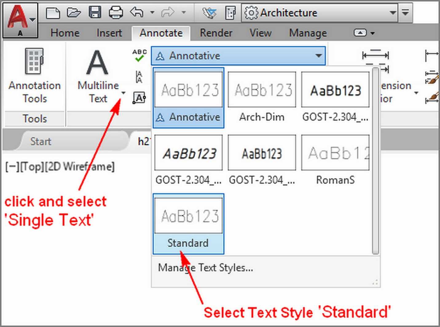
- To Specify on the screen the Start point of text, select a point close to the corner (m1) of the polyline, for Text paper height type 0.27, for Rotation angle of text type 0.00, for TEXT type m1.
Select a second point close to corner c1, and type c1, select a third point close to corner g and type g, select the fourth point close to corner h and type h, click anywhere on the screen and then press Esc to dismiss the SingleText command.
If you wish, you can select the text with your mouse and move it to find its proper position.
Draw the dimensions
Draw the Dimensions (m1 c1) and (m1 h) on the Basement Outline drawing, as shown in Fig.2.1.1.1.
At first, you have to set layer "A-Dim" as the Current Layer, alternatively to the process you followed in the previous paragraph you will follow another way to set the current layer.
- Set layer A-Dim as the current Layer.
To do this: - Click Home tab > Layers panel > click on the Layer properties icon
 and a drop-down menu will open. This menu provides a choice of layer settings defined in the drawing. Select the layer A-Dim, right-click on it, and on the drop-down menu that will open select “Set current”.
To draw the dimension (ah): - Click Annotate tab > Dimensions panel > click on the Linear Dimension icon (hover on)
 . This icon invokes a tool for adding a dimension to the selected object. For the moment don’t use an AEC dimension, just use the tool for linear dimension.
Before start adding dimensions select on the Dimensions panel (icon), and from the drop-down menu the Standard as the default Dimension Style. - To Specify on the screen the first point (m1) of dimension (m1 h), select corner (m1 of the polyline.
- To Specify the second point (h) of dimension (ah), select corner (h) of the polyline.
- To Specify the Dimension location line, select a point upward of line (ah).
Customize Dimension Style
Once you have drawn the dimension, you will notice that its components like text,arrow etc. are very large, or the text is very small. It means that you have to modify the dimension style 'Standard' that you used.
To do this,
- Select a dimension with the style that you want to edit, right-click on it and on the drop-down menu select (hover on)
 tab.
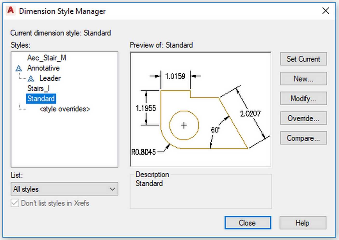
tab. - The dialog box 'Dimension Style Manager' will open, as shown in Fig.2.1.1.6, click on Modify tab to open the dialog box 'Override Current Style: Standard, select on the top tab 'Text' to open the corresponding dialog box, as shown in Fig.2.1.1.7. Here set the text height= 0.15, go back, select tab 'Symbols and Arrows' tab and set Arrow Size= 0.18, go back, select tab 'Primary Units' tab and set Precission= 0.000, go back, select tab 'Fit' tab and on category 'scale for dimension features', set Use overal scale of = 1.000.
- Click OK, and on Dimension Style Manager click Close.
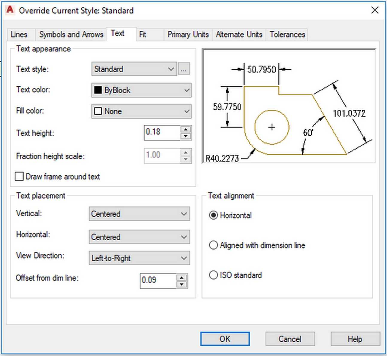
.From now, the 'Standard' Dimension Style on this drawing, has the new values you just inserted.
Save your drawing within folder 'house21-260_custom/basement', with the name: h21260_basem_outline. Its full path will be:
C://ACA/customDwg/house21-260_custom/basement/h21260_basem_outline.
Once you have designed the polyline for the basement outline, you will start designing, at the next step, the exterior walls of the basement, according to the layout and dimensions of the polyline 'Basement outline' as shown in Fig 2.1.2.1.
During the drawing of the Basement Outline, you gave to point (a) coordinates (20, 20) (X=20, Y=20), and keep in mind that you will use these coordinate values for the same point in all floor plans and site plan, you are going to design (See chapter 2.2.1 – Adjust the position of Plans on X-Y plane ….. for more).
Within the folder house21-260_custom you created before, add a new folder named downloads, to have assembled the files of drawings that you will download from the location of the site: www.autocadforum.eu/index.php/downloads, and use these drawings, if you need these, during the design of the project.
The full path of this folder will be: C:\ACA\customDwg\house21-260_custom\downloads.