


At this step, you will draw the architectural plans of the project house21-260, the floor plan of the basement, the plan of the ground floor, the plan of the first floor and the floor plan of the roof - attic. Then you will draw the 2D site plan and the 3D Terrain drawing.
These plans can then be used, with the usual procedure of Autocad Architecture, to create the rest of the architectural drawings such as sections, elevations, 3d Views etc.
The ACA (AutoCad Architecture) software provides special tools to organize your projects so that you can create drawings and project information in the quickest and easiest way. You will apply this procedure during the designing of this project as described in step "4. Drawing Management".
The floor plans and site plans that you will draw in this phase, will be used later in stepr '5' to create the Construct Drawings which form the core of the work drawings.
- Λεπτομέρειες

"Design a House with AutoCad Architecture 2021"
Published - Copyright© 2021 by Pantelis Skourtis
2.1.3 - Basement - interior walls
The final layout of the exterior and interior walls of the basement will be like the one you see in the sketch of the basement (Fig.2.1.3.1). You will follow the dimensions that you see in this sketch to design the interior walls.
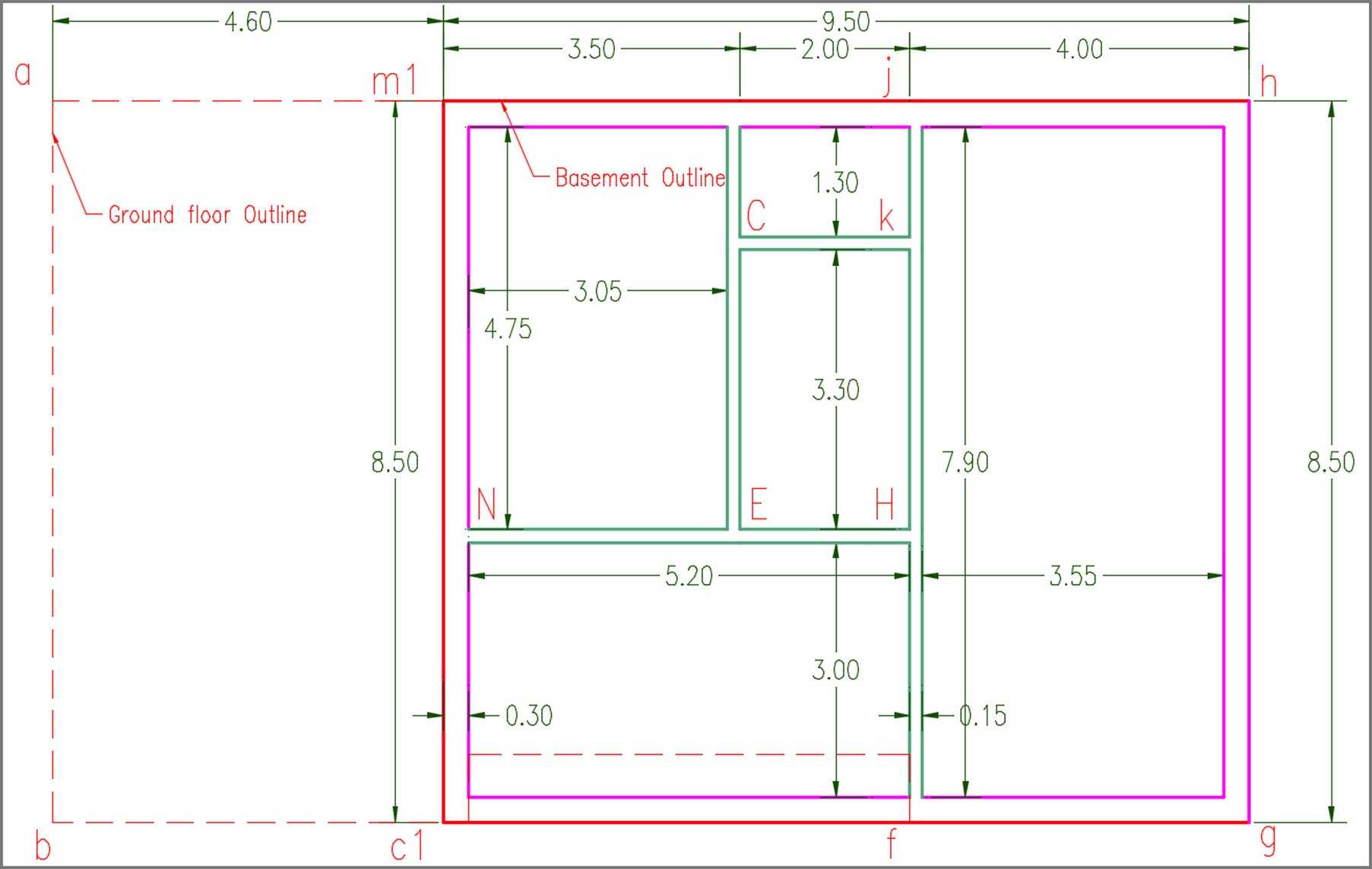
You will start by drawing the walls (NH) and (jf).
To do this:
- Open, with AutoCAD Architecture, the drawing h21260_basem_exterWalls.dwg that you created in the previous step 2.1.2.
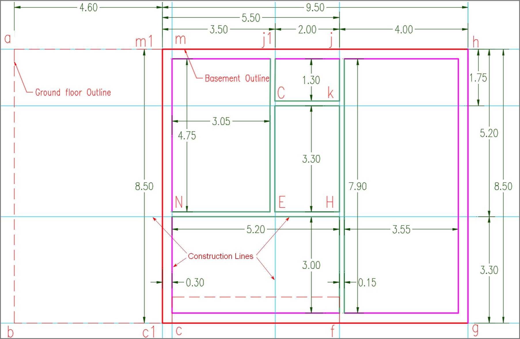
- Draw two Construction lines, one that passes over the line (m1 c1) and one on the line (m1 h) of the corresponding exterior walls (Fig.2.1.3.2)
Construction lines (also known as xlines) are temporary linework entities that can be used as references when creating and positioning other objects or linework.
Construction lines are either circles or straight lines that extend to infinity in both directions.
They do not change the total area of the drawing and do not affect zooming or viewports.
In most cases, you can draw construction lines based on segments of existing objects, but you can also draw them by specifying any two points in the drawing area, without regard to existing objects or linework.
Draw the Construction lines
To use the Construction Lines tool:
- Click Home tab ► Draw panel ► Line drop-down icon (hover on ►)
 ► select Construction Line tool
To Draw the Construction lines: - Select (m1 c1) as linework to create xline (m1 c1), set as offset = 0.00.
- Select (m1 h) as linework to create xline (m1 h), set as offset = 0.00, and press Esc.
- Offset (Fig.2.1.3.2) the Construction line (m1 c1), define as distance 9.50, (is the length of the basement), and select a point near the line (hg) to set the side to be executed the offset command.
- Offset (Fig.2.1.3.2) the Construction line (m1 c1), define as distance 5.50, (is the sum of individual 0.30 + 3.05 + 0.15 + 2.00), and select a point near the line (jf) to set the side to be executed the offset command.
- Offset Construction line (m1 h), define as distance 5.20, (is the sum of individual 0.30 + 4.75 +0.15), and select a point downward of (NH) to set the side to be executed the offset command (Fig.2.1.3.2).
- Offset Construction line (m1 h), define as distance 8.50, (is the width of the basement), and select a point near the line (c1 g) to set the side to be executed the offset command.
Type Text
On Ribbon, set text style Standard as current > set layer "A-Notes" as Current > select on Ribbon the Single Line text tool, (hover on)  , and type the letters N, H, f, j, at the section of construction lines, as shown in Fig.2.1.3.2.
Draw the Walls
Before you continue, create a new layer to use for the interior walls, by name A-Wall-Inter, set as color: 113, and make it current (The reason for creating this new layer, is to distinguish visually the inner from the exterior walls).
- Open the Design Tool palette, find the tool Wall, (this tool 'Wall' uses the wall style standard), press double-click on it to open the panel Properties - Wall (Fig. 2.1.3.3, Fig.2.1.3.4)).
- Scroll down on the left side of the panel to find the field Justify. Press the right field, click the arrow that appears on the right, and select right (Fig. 2.1.3.3).
The justification of the wall determines the side of the wall that we will use as a guide for its placement.
Using the standard style wall, this means that the wall you plan has only one element and consists of only two parallel lines, one right and one left.
With the tool Wall selected,  draw the walls (NH) and (jf) in the direction from N to H, and from j to point f.
- At the prompt: Start point or […]: select point N.
- At the prompt: End point or […]: select point H, and press ENTER.
- At the prompt: Start point or […]: select point j.
- At the prompt: End point or […]: select point f, and press ENTER.
The walls (NH) and (jf) were designed.
Select interior walls (NH) and (jf), their properties will appear in the Properties palette.
With the walls selected:
- In the Properties palette, (Fig.2.1.3.4) set Width to 0.15 and Base Height to 2.80.
These are the dimensions of the real wall that you will use later to replace the 'standard' wall that you used to design the interior walls. - In category Location set Elevation = 0.20, this is the level where the walls will be placed.
-
Fig.2.1.3.3 - Wall Properties - Justify 
-
Fig.2.1.3.4 - Wall Properties - Justify 
To draw the wall (EJ1) (Fig. 2.1.3.2):
- Offset the Construct line (m1 c1), set as distance 3.50, (this is the sum 0.30 + 3.05 + 0.15 of distances between walls (c1 m1) and (E j1), and after adding the thickness of the walls), and choose a point at the right of the line (E j1) to set the side to be executed the offset command. Type the letters E and j1, as shown in Fig.2.1.3.2.
- In the Design Tool palette, click the tool Wall, (you will notice in the Properties palette, that the 'justification' of the wall is 'right', the Thickness is 0.15 and Base Height is 2.80). Draw the wall (Ej1) in the direction from point E to point j1 and press ENTER.
To draw the wall (Ck) (Fig.2.1.3.2): - Apply the Offset command to Construct line (m1 h), set as distance 1.75, (is the distance 0.30 + 1.30 + 0.15 between the walls (m1 h1) and Ck), and select a point to the right of the line (Ck), to set the side to be executed the offset command.
Type the letters C and k, as shown in Fig.2.1.3.2. - On the Design Tool palette, click the tool Wall and draw the wall (Ck) in the direction from point C to point k, and press ENTER.
You have created the interior walls (NH), (jf), (E j1), and (Ck) of the basement plan, which has a thickness of 0.15 m, a Base height of 2.80 m, and an Elevation of 0.20 m.
You placed the walls at Elevation 0.20 instead of 0.00, the reason is that you will add under the walls a floor slab with thickness 0.20 m, whose bottom level is 0.00.
- Set all the interior walls to layer 'A-Wall-Inter'.
- To do this: Select all the interior walls ► right-click ► select Properties ► on the Properties palette that will open, on category General ► select A-Wall-Inter, as the layer of selected walls (Fig.2.1.3.4).
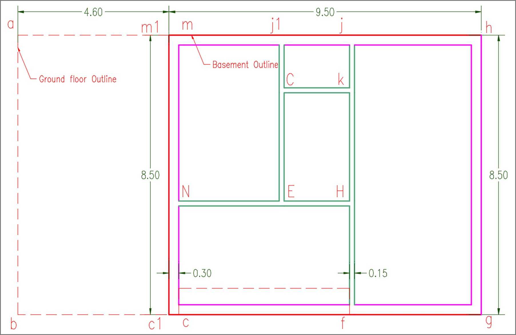
The plan of the basement, after the design of the exterior and interior walls, will be as shown in Fig.2.1.3.5.
Draw the Dimensions
To draw the interior dimensions on the Basement walls drawing, as shown in Fig.2.1.3.1. At first, you have to create a new layer with the name: A-Dim-Details, color: 86, and set it as the Current Layer.
- Set layer A-Dim as the current Layer. To do this:
- Click Home tab > Layers panel > click on the Layer tab (hover on)
 and a drop-down menu will open. This menu provides a choice of layer settings defined in the drawing to make it current. Select the layer A-Dim, to make it current.
 - To draw the dimension (m1 j1):
- Click Annotate tab > Dimensions panel > click on the Linear Dimension icon (hover on)
 . This icon invokes a tool for adding a dimension to the selected object. Before starting to dra dimensions select on the Dimensions panel, 'Standard' as the default Dimension Style.
 - To Specify on the screen the first point (m1) of dimension (m1 j1), select with your mouse the point (m1).
- To Specify the second point (j1) of dimension (m1 J1), select the point (j1) of the wall (m1 j1).
- To Specify the Dimension location line, select with the mouse a point upward of the line (m1 j1).
With the same process, draw the other dimensions, as shown in Fig.2.1.3.2.
The plan of the basement, after the design of the exterior and interior walls, will be as shown in Fig.2.1.3.1.
Save this drawing under the name h21260_basem_walls in the folder customDwg you have created.
Its full path will be: C:\ACA\customDwg\house21-260_custom\basement\h21260_basem_walls
3D Isometric View
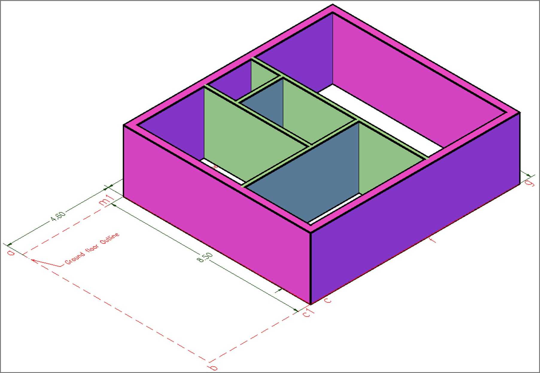
To have a 3D isometric view of your project, on the View Cube tool, at the upper right corner of your screen, click on the corner WS of the Cube.
You can apply a Conceptual style view in your drawing to have a more artistic view:
- To set the Visual Style of the drawing, on Ribbon > click on View tab > click the arrow on Visual panel (hover on )
 , the drop-down which will open provides a choice of visual styles defined in drawing to make current (for the moment the current visual style is the 2D Wireframe) > select Conceptual, to make this visual style current.
The result is shown in Figure 2.1.3.5.
The next step is to place the doors and windows of the basement.
- 2.1.2 - Basement h21260 - Exterior Walls
- 2.1.1 - Basement h21260 - Create the Outline
- 2.2.3 - Ground floor h21260 - Interior Walls -gr
- 2.2.7 - Ground floor h21260 - Exterior stairs - Terraces
- 2.2.7a - Ground floor h21260 - Railings
- 2.2.6 - Ground floor h21260 - Stair
- 2.2.4 - Ground floor h21260 - Doors
- 2.2.4a - Ground floor h21260 - Windows