


At this step, you will draw the architectural plans of the project house21-260, the floor plan of the basement, the plan of the ground floor, the plan of the first floor and the floor plan of the roof - attic. Then you will draw the 2D site plan and the 3D Terrain drawing.
These plans can then be used, with the usual procedure of Autocad Architecture, to create the rest of the architectural drawings such as sections, elevations, 3d Views etc.
The ACA (AutoCad Architecture) software provides special tools to organize your projects so that you can create drawings and project information in the quickest and easiest way. You will apply this procedure during the designing of this project as described in step "4. Drawing Management".
The floor plans and site plans that you will draw in this phase, will be used later in stepr '5' to create the Construct Drawings which form the core of the work drawings.
- Λεπτομέρειες

"Design a House with AutoCad Architecture 2021"
Published - Copyright© 2021 by Pantelis Skourtis
2.2.7a - Ground floor h21260 - Add the Railings
Railings are objects that interact with stairs, and you can add railings to existing stairs.
AutoCAD Architecture provides the tools that let you place railings using a railing tool with specific predefined properties. You can use the default settings of the tool or you can change the properties.
To design the railing of the stairs you will use the Tool Palette - Design (Fig. 2.2.7.11), the style of the railing that is called Guardrail - Pipe.
If there is not this style of railing in the Tool Palette- Design, you will get it from the Content Browser.
To do this:
- On Ribbon > select Tool
 > and from the drop-down menu select Content Browser.
 - On the Content Browser which will open, select > Design Tool Catalog > Stairs and Railing > Railings locate the Guardrail - Pipe Railing icon
 > and select “Add to Tool palette”. The rail style “Guardrail – Pipe” will appear on the Design Tools Palette.
-
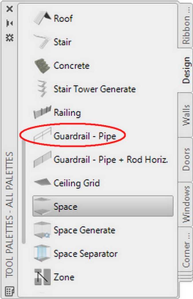
Fig.2.2.7.11 - Tool Palettes - Guardrail - Pipe -

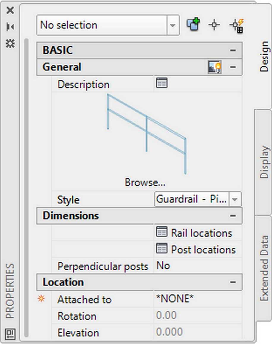
Fig.2.2.7.12 - Properties - Guardrail - Pipe
Design the Stair Railing
- Open the Design Tool Palette, select the railing style Guardrail - Pipe Fig.2.2.7.11).
The Properties Palette of this railing style will open (Fig. 2.2.7.13) where you can edit the values according to your needs.
• In case you use the railing style Standard you have to do the following:
On the Properties Palette (Fig. 2.2.7.13), in category Location make sure that attached is set to Stair and Automatic Placement is set to Yes. In this example you use the railing style Guardrail – Pipe, so you don't need this action. - At the command prompt Select a stair or [….]: select a point on the side (t1 t2) of the stair.
- At the command prompt Select a stair or: select a point on the side (u1 u2) of the stair and press ENTER.
In the same way, design the railing for the exterior stair (v1 v w w1 v1), and interior stair (A B k C A).
The railing of the Stair has been created as shown in (Fig. 2.2.7.14).
Design the Terrace railing
You will design the freestanding railing for the terraces of the ground floor as shown in Fig.2.2.7.16.
The railing of the terraces (a n o h) and (c1 q p f1) will be of style Guardrail - Pipe + Rod Horiz with height 0.90.
- Open, with AutoCAD Architecture, the drawing h21260_groundFloor_stair.dwg that you created in the previous step 2.2.7 or you have downloaded it.
If you wish you can download this file of the ground floor stair drawing, , by clicking here: downloads.
On the website where you will be directed, on category Custom Drawings/ Ground Floor, locate the file h21260_groundFloor_stair.dwg, click on the file name to download it, and then save it under the same name. - Draw the four polylines (b1 r1 t3), (u3 s1 g1), (a1 n14 v), and (w2 o1 h1), they are at a distance 0.10 from the edge of the terrace, as shown in Fig.2.2.7.14.
You will convert these new polylines to add a railing, that has the properties of the railing tool Guardrail - Pipe + Rod Horiz you will select. - Open the Design Tool Palette, right-click on the railing tool Guardrail - Pipe + Rod Horiz Fig.2.2.7.11), click Apply Tool Properties, and select Polyline.
The Properties Palette of this railing style will open (Fig. 2.2.7.13) where you can edit the values according to your needs.
You can use the default settings of the tool or you can change the properties.
If there is not this style of railing in the Tool Palette- Design, you will get it from Content Browser, and drop it in your Tool Palette. - Select the four polylines, (b1 r1 t3), (u3 s1 g1), (a1 n14 v), and (w2 o1 h1), you just created before, as guides for railing, and press Enter.
- At the prompt Erase layout geometry? [Yes No]: Select Yes, and press Enter twice.
The railing on the two terraces has been created.

- Edit the properties of the railing in the properties palette as you wish.
To do this:
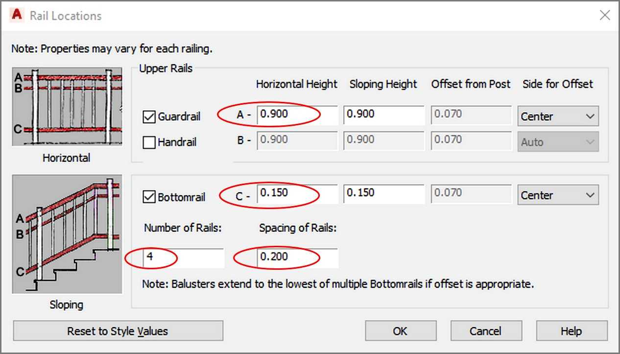
Select the railings that you created, on the properties palette in category Dimensions, select Rail Locations. The Rail Locations dialog box will open (Fig.2.2.7.15), where you will edit the properties of the railing as follows. - On category Upper Rails > Horizontal Height > set for Guardrail A= 0.900, for Bottomrail C= 0.150, set Number of Rails = 4, and Spacing of Rails = 0.20, and click OK.
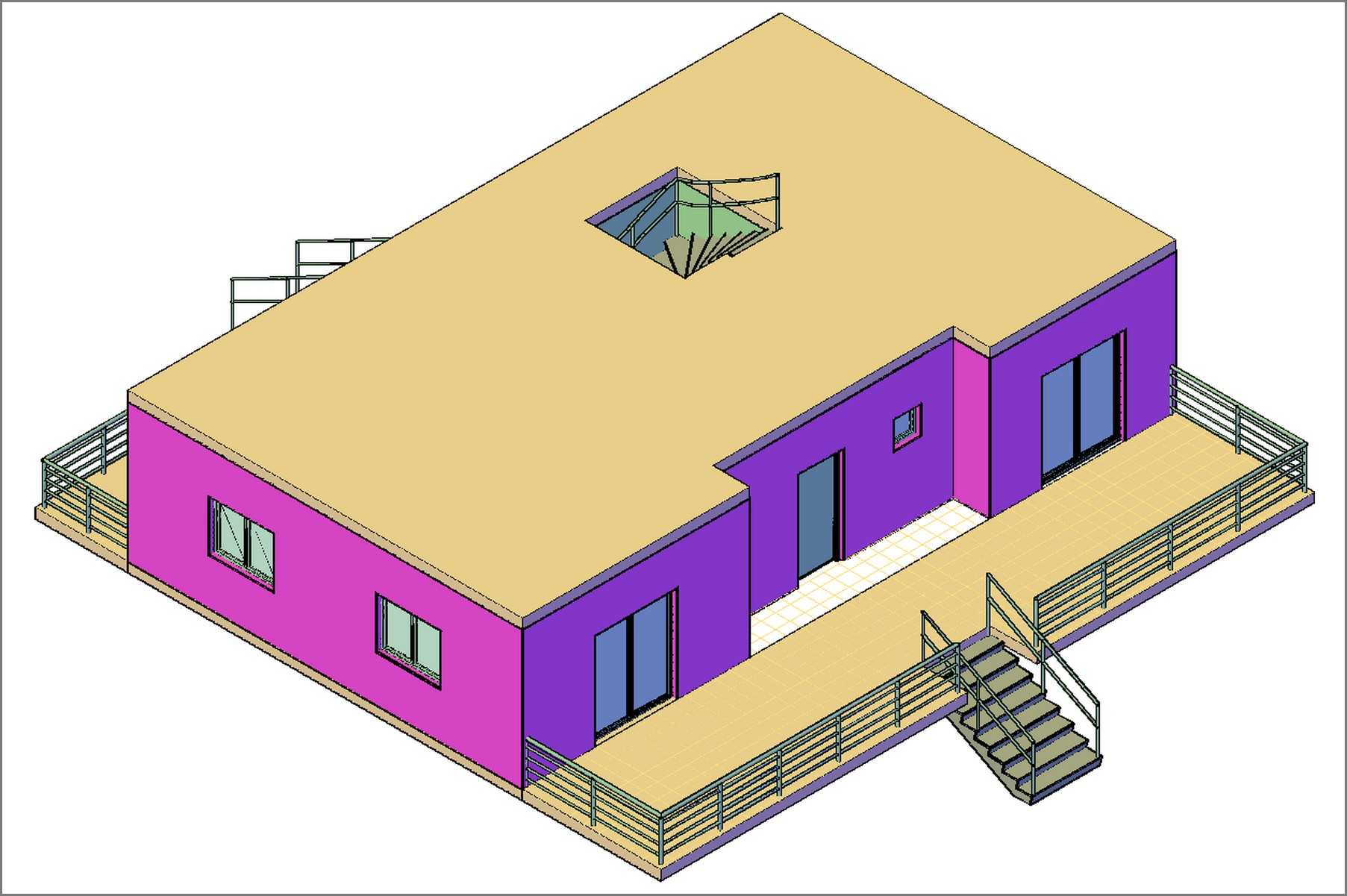
The result (in the 3d view) will be as shown in Fig. 2.2.7.16.
Crete the 3D View in Conceptual mode
- On View Cube, in the upper right corner of your screen, click on the corner WS of View Cube to get a 3D isometric view of your project.
- You can apply a Conceptual view in your plan, to have a more artistic view.
- To do this:
On Ribbon > click on View tab > on Visual panel > > select Conceptual.
The result is as shown in Figure 2.2.7.16.
Save this drawing under the name h21260_groundFloor, in the folder groundFloor, you have created. Its full path is:
C:\ACA\customDwg\house21-260_custom\groundFloor\h21260_groundFloor.
You will use this drawing in chapter 5, to create the ‘construct’ drawings of your project.
- 2.2.6 - Ground floor h21260 - Stair
- 2.2.4 - Ground floor h21260 - Doors
- 2.2.4a - Ground floor h21260 - Windows
- 2.2.3 - Ground floor h21260 - Interior Walls
- 2.2.2 - Ground floor h21260 - Exterior Walls
- 2.2.1 - Ground floor h21260 - Create the Outline
- 2.2.6a - Ground floor h21260 - Open a hole on Slab
- 2.2.5 - Ground floor h21260 - Slab