


"Design a House with AutoCad Architecture 2021"
Published - Copyright© 2021 by Pantelis Skourtis
2.2.5 - Create the Slab of the Ground floor
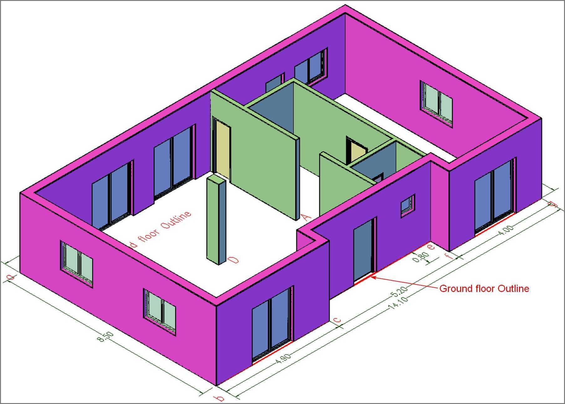
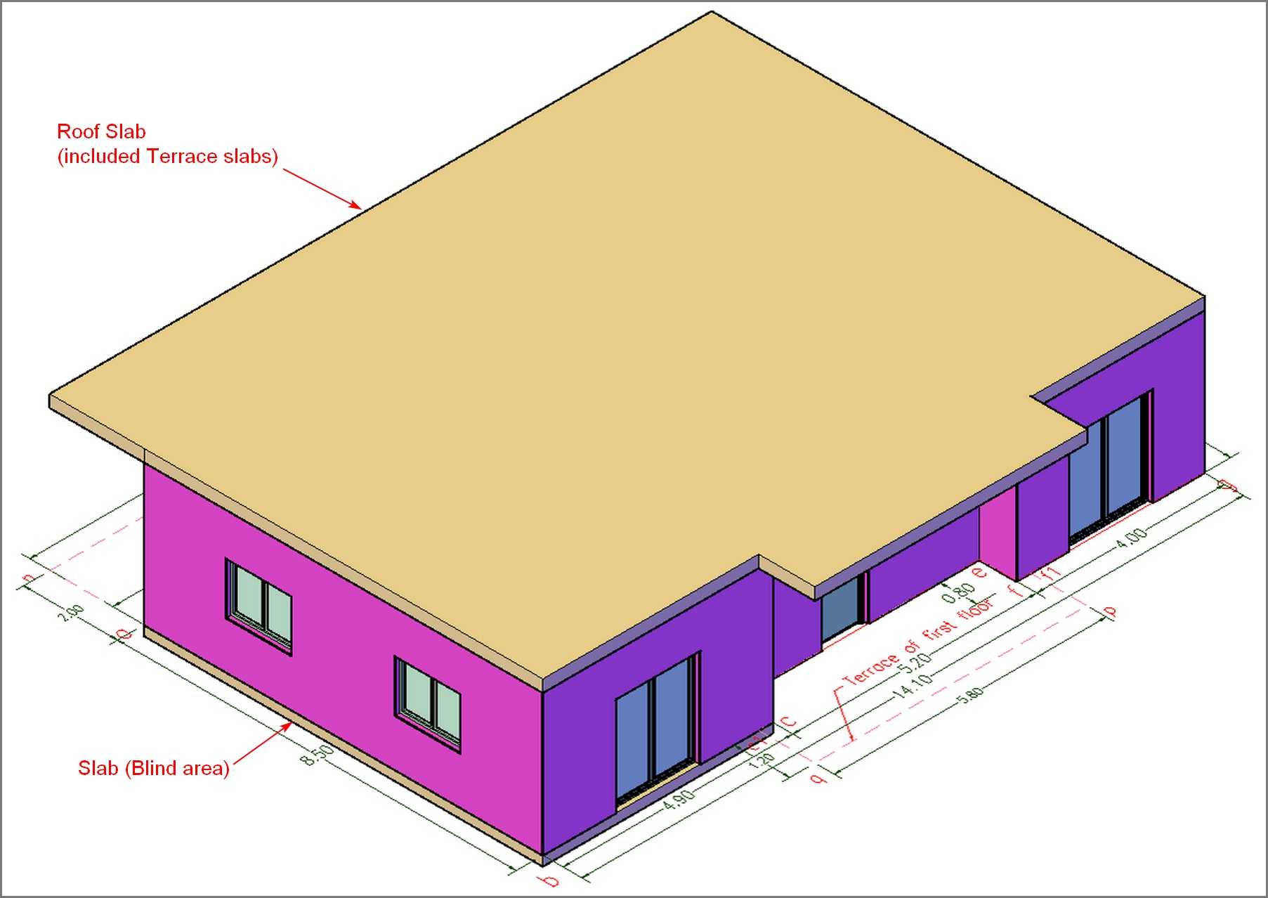
In this step, you will create and place two simple concrete slabs, one on the roof, and one on the blind area of the floor as shown in Fig.2.2.5.4, using the tool Slab.
The roof slab of the ground floor includes also the two terraces of the first floor, as shown in Fig.2.2.5.4.
They will have a thickness of 0.20 (m), and an Elevation of 3.00 for the roof slab, and 0.00 for the floor slab on the blind area.
Open with AutoCAD Architecture the drawing, you created in the previous step, under the name h21260_groundFloor_openings, or if you wish you can download it by clicking downloads. Locate and open it on your screen.
Create the roof slab of the ground floor
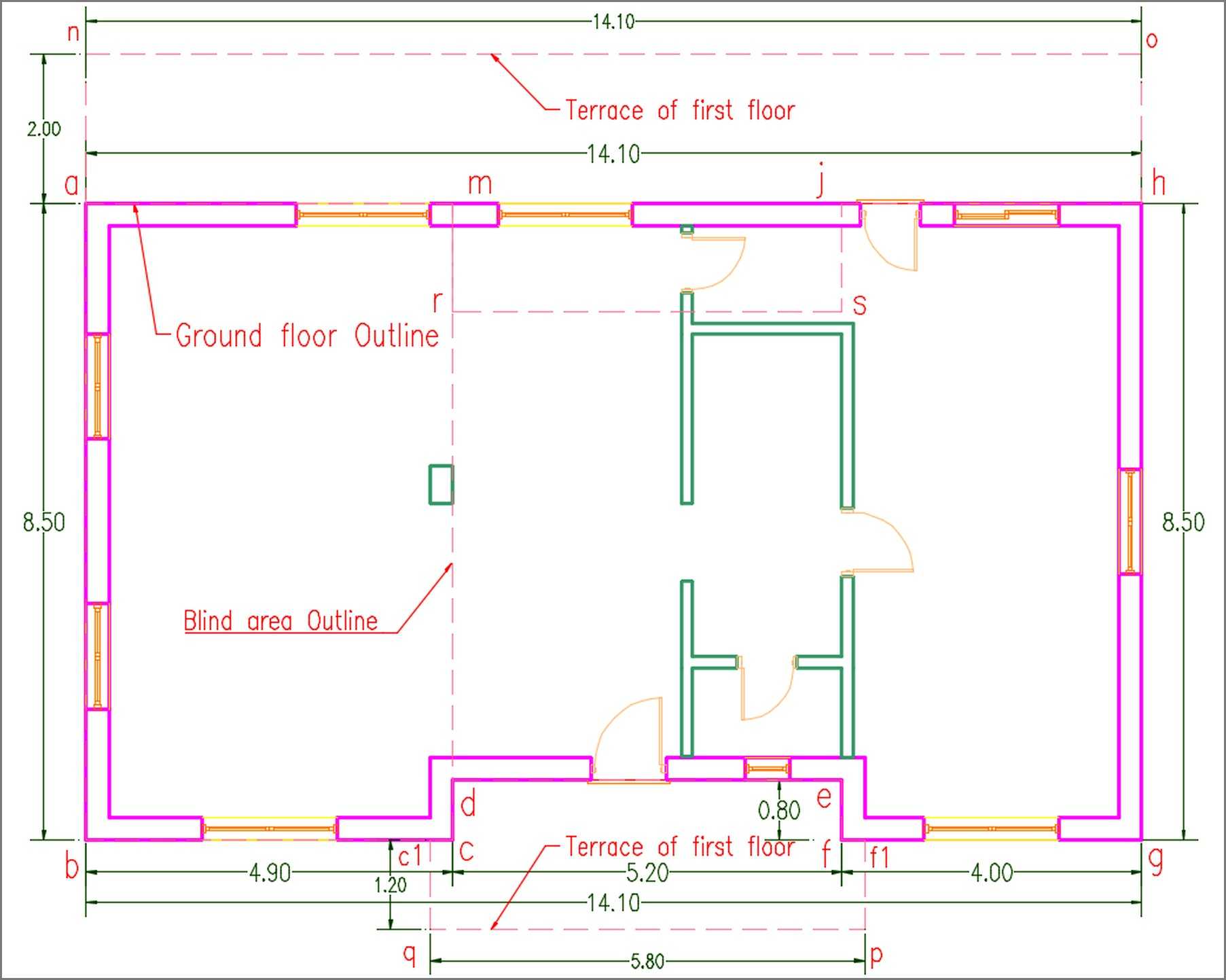
Draw the polylines (c c1 q p f1 f e d c) and (a m r s j h o n a), which describe the two terraces of the first floor, and then draw the polyline (a b c1 q p f1 g h o n a) that is the total outline of the ground floor roof slab, as shown in Fig.2.2.5.0.
You can select the Slab tool on Ribbon > Home tab > Build panel > click the arrow on the icon (hover on ►) >and select Slab, or for this example, you can select it from Tool palette - Design (Fig. 2.2.5.1).
-
Fig.2.2.5.1 - Tool Palette - Design 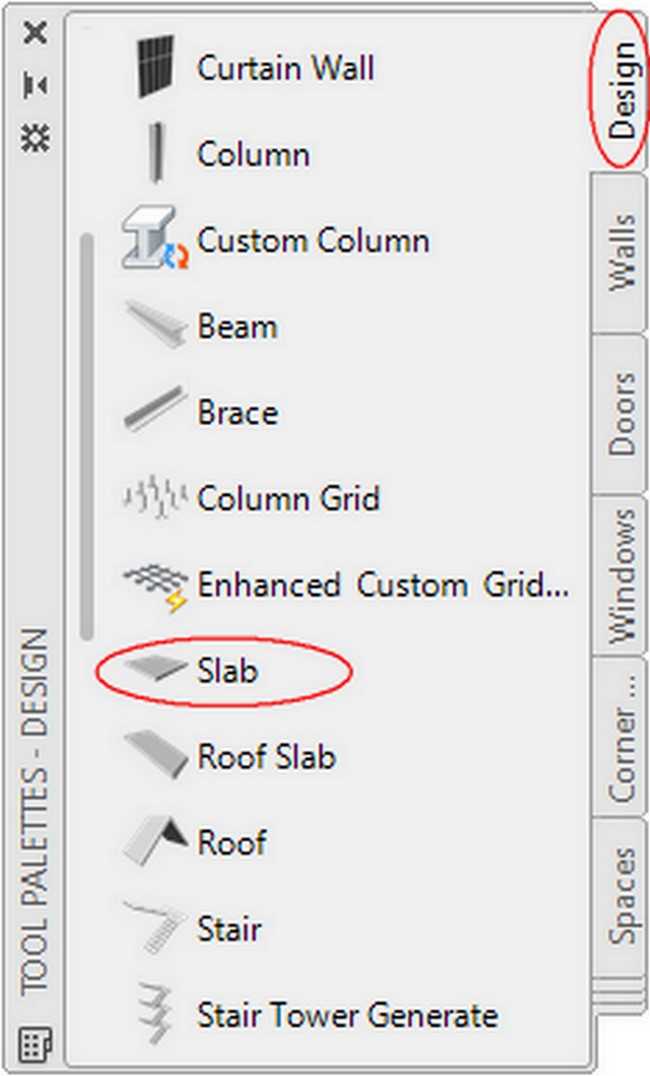
-
Fig.2.2.5.2 - Tool Palette - Design - Slab 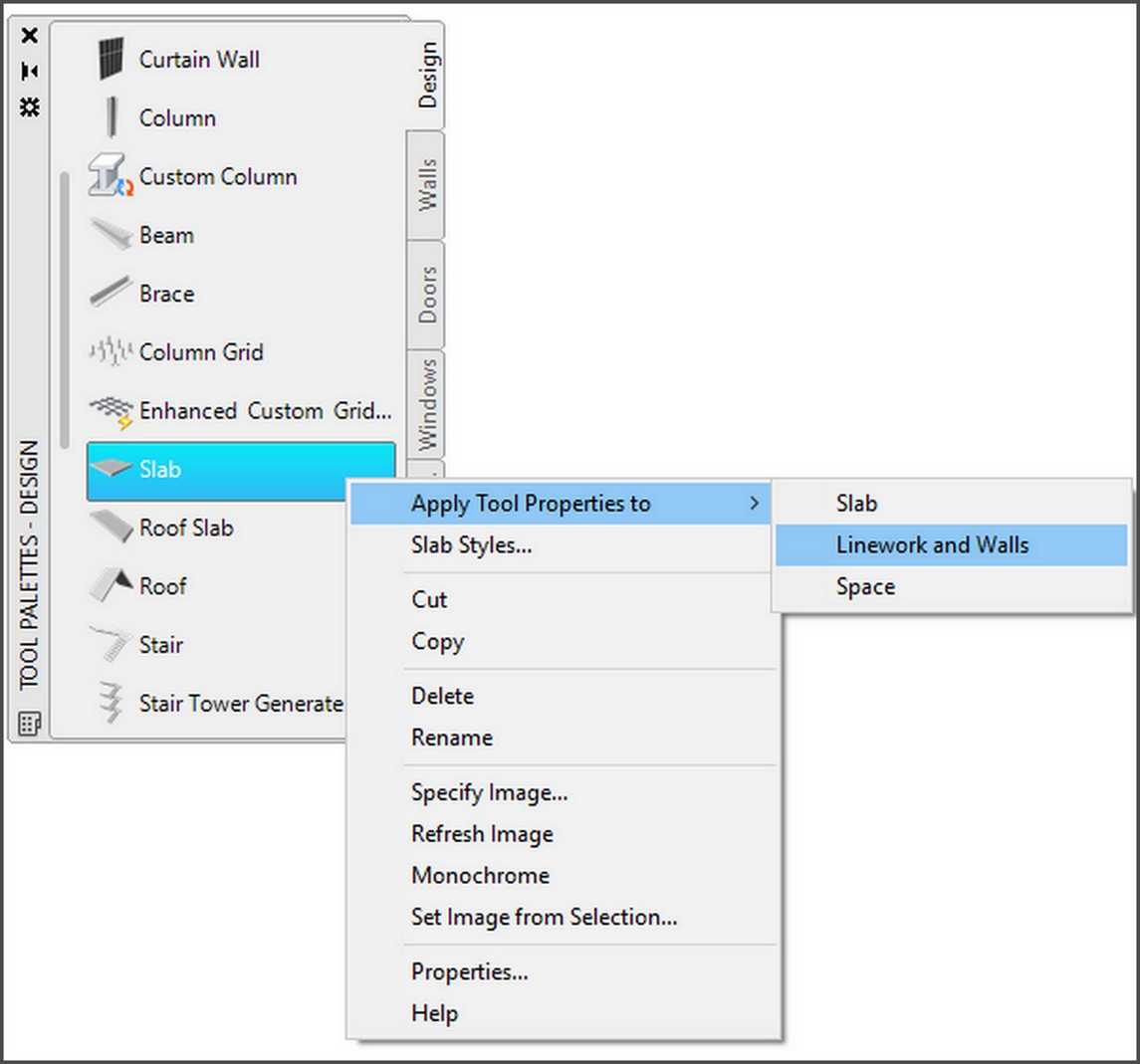
- Locate the closed polyline (a b c1 q p f1 g h o n a), this is the outline of the ground floor, including the two terraces, at level 0.00 (Fig.2.2.5.0), (Fig.2.2.5.3) .
- Open the Tool palettes- Design (Fig. 2.2.5.1) that contains the tool Slab - the slab you want to use - (you may have to scroll to display the desired tool).
- Right-click on the tool Slab, and click on Apply Tool Properties to ► Linework and Walls (Fig.2.2.5.2).
- Select the closed polyline (a b c1 q p f1 g h o n a), and press ENTER.
- Select the closed polyline (abgha), and press ENTER.
It is possible to notice, that you can’t select the polyline, because it overlaps with other objects. Use the Selection Cycling button (on the status),  , which controls the display behavior when you hover over or select an object that overlaps other objects.
This button controls whether a badge or the Selection dialog box displays when you hover over or select an overlapping object.
You can choose between overlapping objects by pressing Shift + Space or by using the Selection dialog box. Make sure that Selection Cycling is turned on.
As you roll your cursor over objects, you will see an icon indicating that multiple objects are available for selection, from these objects select the polyline.
- Press n (No) to keep the polyline in the drawing.
- For the Creation Mode: select p (Projected).
- For Specify Base Height: type the value 3.00.
- For the Specify Slab Justification: select Bottom.
- At the prompt ‘Select the pivot edge of the slab:’ select line (ab) and press ENTER.

- On the Properties palette of the slab that will appear, on category Dimensions locate tab Thickness, change its value to 0.20 (it is, in meters, the thickness of the Ground floor roof slab), on category Location locate tab Elevation, change its value to 3.00, and press Enter and Enter again.
- Before you continue, open the Layer Properties Manager, select layer A-Slab that is created automatically with object slab, click on its color and set it to 21. (The reason for changing the color of the slabs, is to distinguish visually them, while in conceptual view).
The roof slab of the ground floor has been created as shown in Fig. 2.2.5.4.
Create the floor slab (Blind area)
You will notice that in the part (a b c m a) of the ground floor the floor slab is missing because there is no basement below. You need to add this slab to the ground floor.
Draw the polyline (a b c m a) as shown in Fig.2.2.5.3, and create a slab in the area (a b c m a), using the tool Slab and setting as Thickness 0.20, as elevation 0.00, and for Justify set Top. The slab on the ground floor has been created as shown in Fig. 2.2.5.4.
Save the drawing under the name h21260_groundFloor_slabs in the folder you have created earlier. Its full path is:
C:\ACA\customDwg\house21-260\customDwg\groundFloor\h21260_groundFloor_slabs.