


"Design a House with AutoCad Architecture 2018"
Published - Copyright© 2019 by Pantelis Skourtis
In this step, you will create for the project House 21-190 the plans of the first floor, and you will save theese in a folder under the name firstFloor.
The steps to follow are:
- 2.3.1 - Create the first floor outline
2.3.2 - Design the exterior walls
2.3.3 - Design the interior walls
2.3.4 - Place the doors - 2.3.5 - Place the windows
2.3.6 - Create the roof slabs
2.3.7 - Create the interior stair
2.3.8 - Open a hole in the Slab
Within folder C:\\ACA\myProjects\house21_190\customDwg make sure you created a folder called firstFloor. If you have not already done so, you can do it now.
You will use it to store the drawings you will create for the first floor in this phase of designing.
You can also download these drawings from the web site by clicking here: download-dwg-h21190. Save these drawings in the folder downloads, and use them during designing.
The full path of these folders will be respectively: C:\ACA\my_projects\house21_155\customDrawings\firstFloor\ and C:\ACA\myProjects\house21_190\customDrawings\downloads\.
- Details
{jcomments on}
"Design a House with AutoCad Architecture 2018"
Published - Copyright© 2019 by Pantelis Skourtis
2.3.2 - First floor - Exterior Walls
You will draw the exterior walls of the first floor, using as guide the polyline "Ground floor outline"(Fig.2.3.2.1), that you have created at the previous lesson 2.3.1.

- Open, with AutoCAD Architecture, the drawing h21190_firstFloor_outline.dwg that you created in the previous lesson 2.3.1.
- Tool palettes provide the main method for accessing tools to create objects in your model.
The Design Tool Palette includes the basic tools for creating most of the architectural objects. The tools include commands for adding walls, doors, windows, roofs, slabs and more other objects. You can have tools for standard objects as well as for objects with a specific style and properties.
The tool contains creation parameters for the object it represents. When you add an object with a specific tool, the object has the settings you defined in the tool. When you click an object tool to add an object in the drawing, the properties palette opens and you can change properties for the new object if desired. - To open the default Tool Palette - Design group:
- On Ribbon, click the tools icon
 and then on Design Tools tab, (Fig.2.3.2.2), to Open the Design Tool Palette (Fig.2.3.2.3),

- Right click on the tool Wall and select Apply Tool Properties to > Linework (Fig.2.3.2.3).

- At the prompt 'Select lines, arcs, circles, or polylines to convert into walls:', on your screen select polyline 'FirstFloor Outline' (Fig.2.3.2.1), and press ENTER to accept the selection.
- At the prompt: Erase layout geometry: select Yes (or type y), and then press ENTER.
The polyline is replaced by the walls, which are the exterior walls of the first floor plan (Fig. 2.3.2.4).

You will notice that the walls are justified to there center with the First floor polyline, you used to create the walls. You have to justify them to their right, to do this:
With the walls selected, on Properties palette and in Category Dimensions click the arrow on Justify tab, and from the drop-down menu select right.
The position of walls will change, as is shown in Fig.2.3.2.5.

The walls consist of one or more elements, which are the items used for their construction.
The walls used in a drawing have elements and attributes defined by the style of the specific wall tool you selected and used to design it.
Properties of the walls
The Properties palette allows you to view and modify the natural and graphic properties of an object you are going to draw or to select on your screen.
Expanding fields of Properties palette, you can view and modify additional properties of an object that you draw or select.
- Select the walls right click on one of them and select Properties. The Properties palette will open, and display the properties of the selected wall (Fig.2.3.2.6, 2.3.2.7).
-
Fig.2.3.2.6 - Properties of Wall 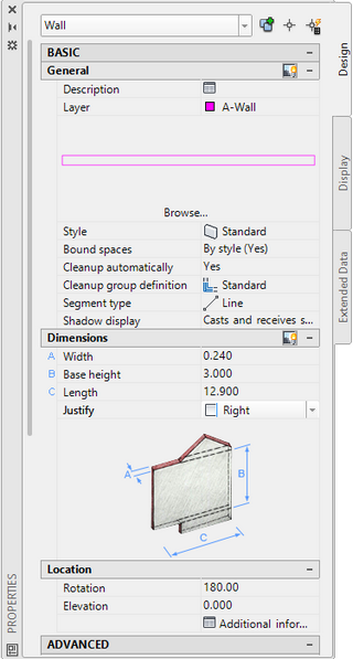
-
Fig.2.3.2.7 - Wall Properties - Justify 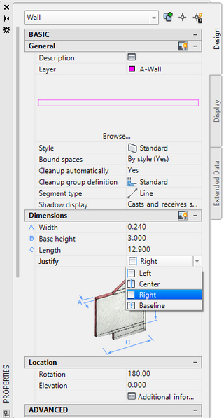
- Look in the properties palette, you'll notice that the style of the wall is the standard, it is the simplest wall style consisting of only two parallel lines that define the two sides of the wall.
It is the wall tool you have chosen earlier from the palette of drawing tools to create the walls.
You will temporarily use this simple style of wall, and later you can replace it with the actual wall style you want to use for the exterior walls of your project. - In category Dimensions select for Justify the value Right (Fig.2.3.2.7). Now pay attention that :
The walls will have the dimensions of the actual final wall you are going to use later, 0.30 for Width and 3.00 for Base Height ( all units are in meters).
The elevation of the walls will be 0.00. It is the level where will be placed the walls. - To do this: In the Properties palette expand category dimensions and set the value of Width to 0.30 and of Base height to 3.00.
The walls have changed and now have Width = 0.30 and Base height= 3.00. - First at the Layers panel click the Layer Properties button
 and on the Layer Properties Manager dialog box locate layer A-Wall, click on its color and change its color to Magenda. (This is done only for better presentation of the plans.)
 - In category Location set Elevation = 0.00.
- You have created in advance the folder: house21_155/customDwg to cluster the plans you will create at this stage of the design (floor plans and site plan).
The full path of this folder is: C:\ACA\myProjects\house21_190\customDwg.
In this folder create four sub folders with names: basement, groundFloor, firstFloor, roof, and sitePlan, where you will save the relevant drawings that you are going to create in this phase of the project. -

Fig.2.3.2.8 - House21-190 - The Dwg folders
Press Esc and save your drawing under the name: h21190_firstFloor_exterWalls
in the folder: C:/ACA/myProjects/house21_155/customDwg/firstFloor
3D Isometric View
To have a 3D isometric view of your project, on the View Cube tool, at the upper right corner of your screen (Fig.2.3.2.9), click on the corner WS of the Cube.
You can apply a Conceptual view in your drawing to have a more artistic view. To do this:
- To set the Visual Style of the drawing, on Ribbon > click on View tab > click the arrow on Visual panel, the drop-down which will open provides a choice of visual styles defined in drawing to make current (for the moment the current visual style is the 2D Wireframe) > select Conceptual, to make this visual style current (Fig.2.3.2.9).
The result is what you see in Figure 2.3.2.9.

Design the Railing of the First floor terrace
The railing of the terraces (AabA1A) and (cdefc) consists of a solid part, that is a wall with thickness 0.20 and height 0.30, and a railing of style Guardrail - Pipe + Rod Horiz with height 0.70.
First you will design the walls, as you designed the exterior walls.
Then select these walls (Aa), (ab), (bA1) and (cd), (de), (ef), their properties will appear in the Properties palette.
With the walls selected, in the Properties palette change the layer name to A-Wall-Inter, the Thickness to 0.200 and Base Height to 0.300.
These are the dimensions of the walls forming the solid part of the railing of the first floor terrace.
Draw the two polylines (AabA1A) and (cdefc), offset them inside the terraces, setting as distance 0.10, you will convert these new polylines to railing that has the properties of the railing tool Guardrail - Pipe + Rod Horiz you selected. After that, erase the two polylines (AabA1A) and (cdefc), you don,t need them any more.
You can edit these properties after creating the railing.
Add the Railing
Railings are objects that interact with stairs and you can add railings to existing stairs, or you can create freestanding railings. AutoCAD Architecture provides the tools that let you place railings using a railing tool with specific predefined properties. You can use the default settings of the tool or you can change the properties.
- To design freestanding railing for the terraces of this plan, you will use from the Tool Palette - Design (Fig. 2.2.9.11), the style of railing called Guardrail - Pipe + Rod Horiz. If there is not this style of railing in the Tool Palette- Design, you will get it from Ribbon > Tools
 > and select Content Browser. you will import this from Content Browser in to your Tool Palette-design.
 - To do this: On the Content Browser which will open, select > Design Tool Catalog > Stairs and Railing > Stairs
 > select the Guardrail - Pipe + Rod Horiz Railing icon, and drag it with your mouse on the Design Tools Palettes.
Open the Content Browser (Fig. 2.2.9.0) > Design Tool Catalog > Stairs and Railing > Railings > select the Guardrail - Pipe +_ Rod Horiz railing (Fig. 2.2.9.11), and i-drag it with the mouse in the Design Tools Palettes.

To design the railing:
- Open the Design Tool Palette, right-click on the railing tool Guardrail - Pipe + Rod Horiz Fig.2.2.9.11), click Apply Tool Properties and select Polyline.
- Select the two polylines you just created as guides for railing, and press Enter.
- At the command prompt Erase layout geometry? [Yes No]: Select Yes, and press Enter twice.
- The railing on the two terraces have been created as shown in (Fig. 2.2.9.13).
- Edit the properties of the railing in the properties palette as you wish.

To do this:
- Select the rails that you created, right-click anywhere on the screen, and on the window that will open, select Editing Rail Style.
- The Railing Styles - Guardrail - Pipe + Rod Horiz dialog box will open (Fig.2.3.2.0), where you will edit the properties of the railing.
- Click tab Rail Locations, on category Upper Rails > Horizontal Height > set for Guardrail A= 1.000, for Bottomrail C= 0.375, set Number of Rails = 7, and Spacing of Rails = 0.100, and clicl OK.
The result will be as shown in Fig. 2.3.2.11.

The next step is to design the interior walls of the First floor.